Noise generator
When a test setup needs controlled randomness rather than a perfectly clean signal, the right source becomes just as important as the measurement instrument itself. Noise generator products are used in telecom, RF, and optical environments to introduce a defined noisy signal, simulate real operating conditions, and verify how systems respond under less-than-ideal inputs.
On this page, the category covers several practical directions of noise generation, from optical “noise eater” style devices used to stabilize laser output to RF broadband noise sources and tone generation tools for cable tracing and continuity work. That makes the selection especially relevant for engineers, laboratories, system integrators, and maintenance teams working across communication infrastructure and photonics.
Where noise generators are used in practice
In telecommunications and electronic measurement, noise is not always something to remove. In many workflows, it must be created deliberately so teams can evaluate sensitivity, stability, attenuation behavior, or fault response. A controlled noise source helps reveal how a receiver, link, optical path, or test circuit behaves when signal quality changes over time.
Typical use cases include broadband RF testing, optical power stabilization, signal path verification, and maintenance of structured cabling. In broader test chains, these devices may be installed alongside components such as isolators or a power divider to build a more complete telecom measurement setup.
Optical noise control and laser intensity stabilization
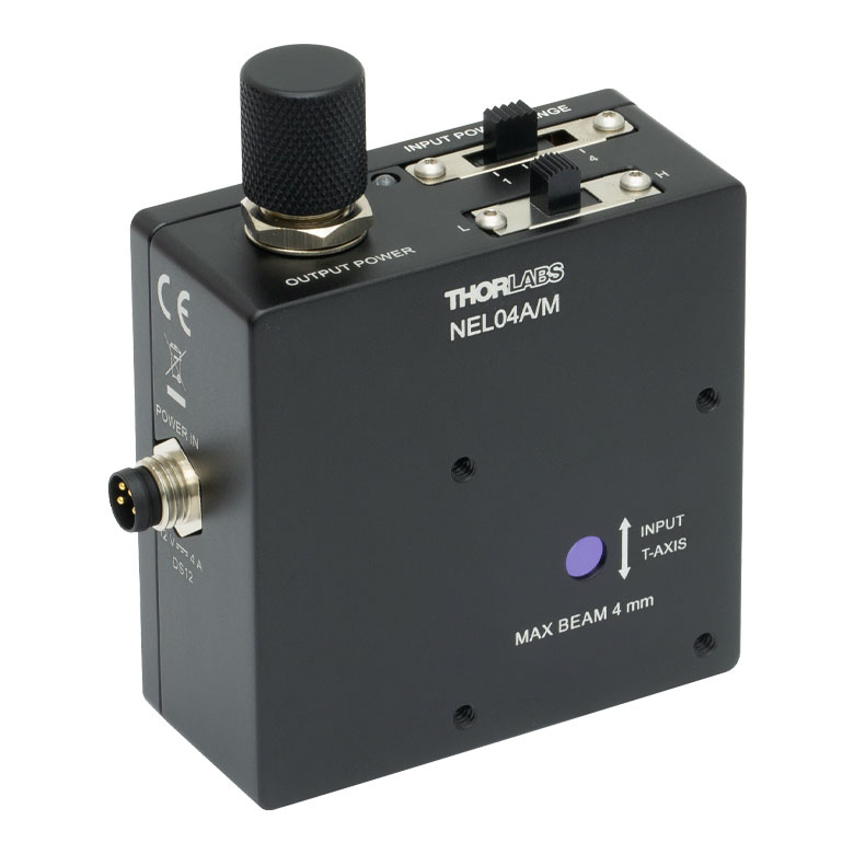
A major part of this category is represented by optical noise control devices from THORLABS. In this context, the products are not broadband lamps or random light emitters; they are designed to reduce intensity fluctuations in a laser beam, helping improve output stability over time. This is especially important in photonics experiments, detector characterization, and optical benches where amplitude noise directly affects repeatability.
Models such as the THORLABS NEL01A, NEL02A, NEL03A, and NEL04A families cover wavelength regions from the visible band up to 1620 nm. Across these ranges, the devices are intended for attenuation control and suppression of low-frequency power fluctuations, with control via onboard adjustment or SMA modulation input depending on the setup requirement.
Optical noise attenuation is particularly useful when laser-based measurement systems need a more stable beam for calibration, comparison tests, or long-duration experiments. Instead of manually compensating for source drift, engineers can integrate a dedicated module into the optical path and maintain a more consistent output.
Representative models in this category
For visible wavelengths, the THORLABS NEL01A and NEL02A series address applications roughly from 425 - 650 nm and 475 - 650 nm. For red to near-infrared work, the NEL03A series supports 650 - 1050 nm, while NEL04A variants extend into 1050 - 1620 nm. M4 and 8-32 tapped versions are available among the listed products, which is relevant when matching the device to an existing mounting standard.
These optical units share several characteristics that matter in real integration work: broad wavelength-specific coverage, compatibility with common mounting arrangements, and support for controlled attenuation ranges. The published data also indicates stable output behavior and defined noise attenuation performance across a low-frequency range, which is often where laser intensity drift becomes troublesome.
Outside photonics, the category also includes the Promax NG-283, an RF white Gaussian noise source covering 1 MHz to 2200 MHz. This type of instrument is more suitable for CATV, RF distribution, and broadband telecom testing where frequency response, flatness, and spectral density matter more than beam handling or polarization behavior.
Noise generation for cable tracing and field service
Not every noise or tone source is intended for laboratory simulation. In field service and network maintenance, technicians often use a tone generator to identify cable pairs, check continuity, and verify polarity. The Fluke Network 26200900 Tone Generator is an example of this practical segment, combining tone and continuity functions for troubleshooting copper infrastructure.
This type of tool serves a different purpose from optical or RF noise sources, but it belongs in the same broader selection logic: generating a known signal so a user can trace, identify, or validate a path. In installations that also involve line matching or signal distribution hardware, related components such as balun devices or telecom switches may appear elsewhere in the system.
How to choose the right noise generator
The most important factor is the signal domain. Optical labs should focus on wavelength range, attenuation behavior, mounting compatibility, and modulation interface. RF users should pay more attention to frequency range, output level, flatness, and impedance context. For cable maintenance, the practical concerns are mode selection, protection level, portability, and clear indication of continuity or tone status.
It is also important to consider how the device will be installed. Some optical models in this category support standard post mounting, cage system integration, or lens tube compatibility. That matters when the generator is part of a fixed experimental rig and not just a benchtop accessory.
Control method is another useful filter. If a setup requires external modulation or automated adjustment, products with SMA input are more suitable than units limited to manual control. If the requirement is basic troubleshooting in the field, a simpler handheld tone generator may be the more efficient choice.
Key technical points worth checking
Before selecting a model, review the parameters that actually affect your workflow rather than comparing products by name alone. For optical equipment, users commonly compare wavelength band, minimum input power, attenuation range, polarization-related behavior, and supported frequency range for noise suppression. For RF devices, the practical comparison usually centers on usable bandwidth, flatness, and output power characteristics.
- Wavelength or frequency coverage matched to the system under test
- Output stability for repeatable measurement results
- Interface and control such as potentiometer adjustment or SMA modulation input
- Mechanical compatibility with existing fixtures, mounts, or benches
- Application type: optical stabilization, RF simulation, or cable tracing
This approach helps avoid overbuying a device with the wrong operating principle. A broadband RF noise source, for example, is not interchangeable with an optical noise attenuation module, even though both appear under the same category heading.
Why manufacturer context matters
Within this category, the listed brands reflect clearly different use cases. THORLABS is the primary reference for optical beam stabilization and noise attenuation in photonics environments. Promax is more aligned with RF and television or broadband signal applications. Fluke Network fits cable identification and maintenance workflows rather than optical bench work.
That distinction is useful for procurement teams and engineers who need to shortlist products quickly. Instead of comparing all models at once, it is often more efficient to begin with the intended test environment, then narrow the search by manufacturer specialization and finally by core operating range.
Finding the right fit for your setup
A suitable noise generator should match the physics of the signal path, the control method used in the test bench, and the level of repeatability the application demands. Whether the goal is stabilizing a laser source, injecting RF noise across a wide band, or tracing telecom cabling in the field, the right product is the one that supports the actual measurement task without adding unnecessary complexity.
This category brings together those use cases in one place, making it easier to compare optical, RF, and service-oriented signal generation tools side by side. If you are refining a telecom or photonics test setup, start with the operating range and application type first, then review the available models for mounting, control, and integration details.
-
-
-
-
-
-
-
-
-
-
-
-
-
-
-
-
-
-
-
-
-
-
-
-